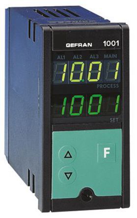
• 1200 / 1300 TEMPERATURE CONTROLLER INSTRUCTIONS FOR USE AND WARNINGS Software Version 4.0x code 81801G / Edition 08 - 07/2011 ENGLISH GENERAL INDEX page page Application notes Graphic symbol used Preliminary instructions HB Alarm General description HOLD function Basic version controller. • They represent an exclusive combination • 1 universal input for TC, 2/3 wire RTD, PTC, NTC, performance, reliability and applicational flexibility. In particular, this new line of Gefran tempera- and linear thermocouples, supplied with current and ture controllers is the ideal solution for application voltage with accuracy better than 0.2% f.s.

Contact GEFRAN for more information on control actions. 9 • MANUAL TUNING A) Enter the setpoint at its working value. Page 14 12 • SELF-TUNING The function works for single output systems (heating or cooling).

• Lexan that guarantees IP65 level protection. • Mains voltage supply • 4 buttons to be used for manual regulation/ Example: 1200 – RT – RR – 00 – 0 – 1 configuration/selection Model 1200 controller • 2 green four-digit displays Output 1 - Relay; Output 2 - Triac (1A) (Process Variable and Set point Variable) Output 3 - Relay. • 2 • INSTALLATION AND CONNECTION This section contains the instructions necessary damage to persons, machinery or materials, it is for correct installation of the 1200/1300 essential to connect it up to auxiliary alarm controllers into the machine control panel or the equipment. • • Fit a 1N4007 diode in parallel with the coil of the - the Ohmic resistance must be 1MW) 5V, 10V (Ri > 10KW) Use wires of adeguate diameter (min.
1mm 2-wire connection 3-wire connection Outputs Out1, Out 2 User configurable generic outputs. • Serial line Modbus 2 wires (Standard) Modbus 4 wires / Cencal RS485 isolated serial line RS485 isolated serial line For configuration Modbus 4 wires/Cencal. (data -) (data +) Example of connection with TC Input Electric heating with power solid state relay and water cooling with solenoid valve OUT1 relay OUT2 logic 81801G_MHW_1200-13_ENG. • This section illustrates the functions and operating modes of the displays, the indicator lights and the buttons that make up the operator interface of series 1200/1300 controllers. It is therefore an essential requirement for programming and configuring the controllers correctly.
• General Operating Notes Switching on and using the Controller Self-diagnostics • Immediately after switching on the controller carries out a self-diagnostic test. During the test, all the display segments and the 7 indicator lights will flash. • If the self-diagnostics procedure does not detect any errors the controller enters the normal working status (Level 1) • Any errors found by the self-diagnostics are memorized in a record and can be displayed with the ERR function in the INF menu Normal Working - Level 1 PV Displays the value of the Process Variable. Uss constitution. • Navigating through the Controller Menu Keep pressed down to scroll through the menus in sequence and release it when the required menu appears.
Press to access the parameters of the selected menu. Keep to return immediately to level 1. Level 1 Display Menu 39. • Integral heating time [0.0. Marvel ultimate alliance wii ntsc iso torrents. 0 0 Optimal working operation of the 1200/1300 Controller in the field of application it is intended for depends largely on correct (default value) configuration and programming of the relevant control parameters.
• EASY Configuration/Programming Standard for instrument with 2 Outputs: OUT1 = AL1 / OUT2 = MAIN HEAT In the EASY configuration, the general navigation flow shown at the end of Section 3 - Functions is considerably simplified, as illustrated in the following figure. Level 1 display Menu 39. • -Easy- Configuration Fourth menu to set up This menu is used to configurare the control parameters in the Easy mode. S.tun Continuous Selftuning Softstart autotunig Enabling self-tuning, autotuning, S. V softstart (**) S.tun Single action Selftuning Softstart Autotuning WAIT WAIT WAIT *) By adding the following figures to the value indicated in the table it is possible to enable a series of supplementary functions. • -Easy- Inputs Settings Third menu to set up Probe type Without dec.