Do you have a means of reading the encoder? Is it absolute or incremental?
The thing you have to be careful of is delays - delays make a control loop less stable, so you really want to measure the timing of successive encoder pulses directly and use that, but there will be jitter (noise) too. Trying to average out the noise by timing several pulses will increase the delay which changes loop stability. Reducing loop gain will make it stable, but the system will be slower to respond to changes of load. Have you used a PID loop before? If not read up about them. Do you understand what PID is? If you are able to use the sensor to get accurate measurements of the motor's shaft velocity (or a value that is proportional to the velocity), then you know how to use that information to control the speed of the loaded motor, right?
Using the motor with a load is typical. Normally, a system designer will try find out information about how the motor behaves without a PID controller, like maybe do a 'step response' test to get basic parameters (like first order system parameters) to work with. Otherwise, there's the other approach, where the P and I and D constants are twiddled by trial and error to try find values that provide a suitable overall system behaviour. When the P and I and D values are settable with software (in the software code), then it's normal to use a particular set of PID values for a particular range of loads. Statji po psihologii na anglijskom yazike s perevodom 3.
Code with the Arduino. At the beginning of program, it will receive commands from the computer (start/stop motor; motor speed settings; kP, kI, kD gain of PID). Next is void detect_a(): which is an encoder for sum calculation used for speed calculation in the Timer interrupt routine.
And if the system knows that the load changes significantly, then somehow the system might need to be amended to use a different set of PID values (which is basically changing the control system). We really need a bit more information to say much about the regulator or regulators you use. I get the feeling from what you've already said that the 'encoder' is a pulse tach so if true that is a start. Beyond that what is your power supply?
Flat dc is easiest to work with. If it is single phase rectified dc then the motor current will always be discontinuous and the RPM per PWM duty cycle is very non linear and this means that if you ever get the P, the I and the D right for one speed they will be wrong for another.

I've been working on this off and on lately (more out of curiosity than necessity) and the approach of the moment is an internal voltage regulator which implies the need for a voltage feedback and a speed regulator around this; each of these two regulators could be implemented via the PID algorithm. In the DC drives industry two different approaches are taken: speed/voltage regulator and speed/current regulator. The former is relatively insensitive to load inertia and the latter is sensitive to load inertia but allows implementation of a very smooth transition from speed to torque control--so look at your application and take your choice.
This is the encoder: This is the motor: Power supply will be 12v regulated, 5amp. There are two limit switches, one on each end of the range of motion. Is there a PID resource that someone can recommend? I'd like to know a bit more about it. 
It seems like it could be useful in my situation, but it's also seeming like it may not be worth the effort. Anyway, if I can control the motor with pid, I'd like to maintain about 90 rpm with current control. (At its peak the motor draws 3-4 amps).
This is standard control theory. If you want a stable controllable speed irrespective of load you're building a velodyne. I suggest a simple hardware approach is easier and cheaper than than using a processor.
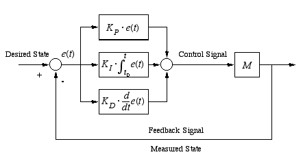
I've done it both ways! I take it you know that PID stands for proportional, integral and differential - a 3 term controller.
Proportional: the bigger the error, the higher the correctional force you supply Integral: close to the required value you integrate the error over time to give a 'zero' final error. Differential - as you approach the wanted value, you reduce the force to reduce / eliminate overshoot.
A simple op-amp can do all of this. If you want want to do it with a processor you must sample very much faster than the time constant of the system. In any case you need to know the transfer function of the system ie how quickly the speed changes with a change of load and of supplied force for details go to college and learn the Laplace transform and it's use in various approaches - eg Nichols, Nyquist, Bode etc. And watch out for stability!
Most Viewed News
- Download Free Microsoft Image Composer 15 Software
- Eyeshield 21 Full Episodes Torrent Download
- Inpa Software Bmw E39
- Casparcg Live
- Billa Prabhas 2009 Full Movie Download 300 Mb In Hindi
- Samsung 2g Tool Cracked Software Without Z3x Box Price
- Honeywell Scanning And Mobility Hsm Usb Serial Driver
- Conflict Desert Storm 3 Pc Game Free Download
- Style Works 2000 Korg Pa With Crack Keygens
- Huawei B593 Driver Firmware Download 2016